
Choosing a Step Up Transformer is not just a matter of matching two voltage numbers. The right choice must also suit the load, supply frequency, operating environment, and protection system. A unit that looks adequate on paper may overheat under continuous duty or struggle with motor-starting current. Small details matter.
The stakes are growing. The International Energy Agency’s 2023 report, Electricity Grids and Secure Energy Transitions, says annual grid investment needs to rise from roughly $300 billion to more than $600 billion by 2030. That figure covers grids overall, not transformers alone, but it highlights the pressure to plan equipment carefully. Electrical-machines author Stephen J. Chapman defines a transformer as “a device that changes ac electric power at one voltage level to ac electric power at another voltage level through the action of a magnetic field.” The definition is simple. Applying it well takes more care.
This guide explains how to compare transformer capacity, voltage ratio, impedance, cooling, insulation, and efficiency. It also considers harmonics, inrush current, site conditions, and future load growth. For example, a workshop transformer feeding a motor may need different allowances from one serving steady lighting loads. Check the nameplate, wiring diagram, and manufacturer’s test data; do not rely on a seller’s headline rating alone. The margin is thin. A precise calculation still depends on real operating conditions, and those are sometimes poorly documented. That uncertainty deserves attention, not a guess.
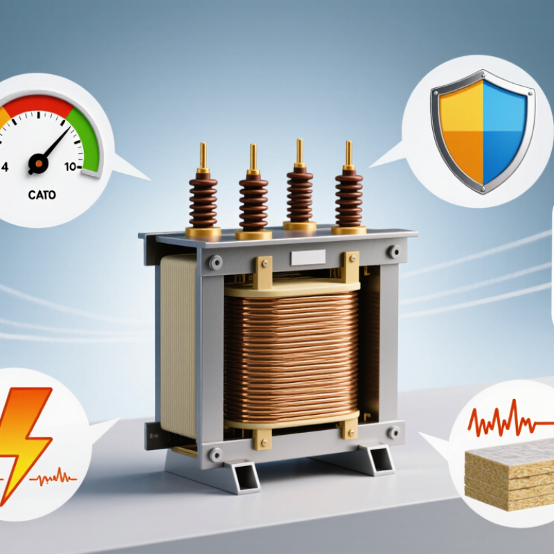
A step-up transformer raises voltage while reducing current for a given amount of power. At a generating site, it can take electricity at a lower voltage and deliver it at a higher transmission voltage. This matters because power lines lose energy as heat, and those losses rise with current.
The U.S. Energy Information Administration reports that transmission and distribution losses averaged about 5% of electricity supplied annually in recent years. That figure covers the whole grid, not transformers alone. A step-up transformer helps manage one part of the problem.
Inside the unit, alternating current creates a changing magnetic field in the core. This transfers energy between windings, which have different numbers of turns. More turns on the output winding produce a higher voltage. Simple in principle.
In a substation, the transformer may sit behind fences beside large insulators, with cooling equipment moving heat away from its core and coils. Its rating, insulation, cooling method, and expected load all matter when choosing one. The simple picture has limits: actual voltage can vary with load, and a transformer does not create extra power. Engineers also check site conditions and protection requirements. A specification can look right on paper and still miss a practical detail.

Before choosing a step-up transformer, write down the source voltage and the equipment’s required voltage. Check the source at the connection point, not just a utility bill or an old drawing. A nominal 120 V supply, for example, may need to be raised to 240 V for a specific load. Read the equipment nameplate carefully. It may specify voltage, phase, frequency, and an acceptable voltage range. Small mismatch, big trouble.
Then match the transformer’s primary and secondary ratings to those values. Confirm whether the source is single-phase or three-phase; a voltage match alone is not enough. Consider the load’s starting current and expected voltage drop, especially for motors or long cable runs. Measure under load where practical. I still verify this twice, because nameplates and site wiring do not always tell the same story. The U.S. Department of Energy’s 2024 distribution-transformer standards analysis projects 10.9 quadrillion Btu in energy savings over 30 years. That figure covers efficiency standards, not voltage selection, but it underlines why ratings and losses both deserve attention. If the measured input varies, check the transformer’s specified input range and tap settings before ordering.
First, confirm the voltage available from your power source and the voltage required by your equipment. The examples show nominal voltage pairs; choose a transformer rated for your actual input, output, frequency, and load, and verify that the output voltage meets the equipment’s specifications.
How to Choose a Step Up Transformer?
Calculate the Load Capacity and Power Requirements
Start with the equipment’s nameplate, not its appearance or size. Record its input voltage, wattage, and current, then confirm the transformer’s input and output voltages match your supply and load. For mixed equipment, add the loads that may run at the same time. A small workshop might use a 240-volt tool and a heater together; sizing for only one could cause overload.
Transformer capacity is usually listed in volt-amperes (VA) or kilovolt-amperes (kVA), not watts. For a load rated 1,500 watts at a 0.9 power factor, divide watts by power factor: 1,500 ÷ 0.9 equals about 1,667 VA. Choose capacity above this figure, allowing headroom based on the manufacturer’s guidance and how long the load operates. Check the secondary current too: at 240 volts, 1,667 VA draws about 6.9 amps.
A calculation can look perfect and still miss startup current. Motors, compressors, and some power supplies briefly draw more current when switched on. Check their starting requirements before choosing a transformer, and don’t assume a unit rated for the running load will handle the surge. Also verify cooling, duty rating, and installation conditions. When the load data is unclear, pause and confirm it with a qualified electrician.
Choosing a step-up transformer starts with the load, not the voltage ratio alone. Check whether the source and equipment are single-phase or three-phase; mismatching them can add conversion costs or complicate installation. Single-phase units can suit smaller, isolated loads, while three-phase designs commonly serve balanced industrial equipment. Check the nameplate, expected peak demand, and future load growth. Check the load first.
Efficiency depends on both core losses, which occur whenever the unit is energized, and winding losses, which rise with load. A lightly loaded transformer may waste energy through core losses; an undersized one can run hot and incur greater winding losses. The U.S. Department of Energy’s 2016 distribution-transformer efficiency rule projected 3.63 quadrillion Btu in energy savings over 30 years. That is a national estimate, not a promise of savings for one installation. Compare certified efficiency figures at the same rating and test conditions, then estimate performance against your real hourly load. A quick comparison of headline percentages can mislead; I’d want the load profile before choosing.
Choosing a step up transformer starts with the load, but safety deserves equal attention. Confirm the source voltage, required output voltage, frequency, and total load. Motors and pumps can draw much more current when starting, so their nameplate rating alone may not tell the whole story. Allow suitable capacity for startup demand and future equipment. Small details matter.
Check the transformer’s enclosure, grounding provisions, and overcurrent protection before installation. Place it on a stable surface with enough clearance for airflow and servicing. Follow the manufacturer’s wiring diagram, and have a qualified electrician verify connections and protective devices. Keep cables away from hot surfaces and walkways. A neat installation is safer, though neat wiring alone does not prove a system is correctly protected.
Environmental conditions can change the choice. Heat, moisture, dust, corrosive vapors, and altitude may affect cooling or insulation performance. Match the enclosure and operating ratings to the actual location, such as a damp utility room or a dusty workshop. One point is easy to underestimate: ventilation needs can conflict with keeping dust out. Check the specified limits rather than guessing, and reassess them if the installation site changes.
| Selection Dimension | What to Check | Practical Guidance | Why It Matters |
|---|---|---|---|
| Input and output voltage | Supply voltage, required load voltage, and whether each is single-phase or three-phase. | Choose a transformer with the correct primary and secondary ratings. Confirm that the input supply matches the primary connection and that the secondary voltage suits the equipment. | A voltage or phase mismatch can prevent operation or damage connected equipment. |
| Frequency | Confirm the supply frequency and the transformer’s rated frequency, such as 50 Hz or 60 Hz. | Use a unit rated for the actual supply frequency. Do not assume a transformer designed for one frequency is suitable at another without checking its rating. | Frequency affects magnetic flux and can influence heating and performance. |
| Load capacity (kVA) | Calculate the connected load’s apparent power, including voltage, current, power factor, and phase. | Select a kVA rating that accommodates the expected continuous load. For a single-phase load, kVA = volts × amps ÷ 1,000. For a balanced three-phase load, kVA ≈ √3 × line volts × line amps ÷ 1,000. | An undersized transformer can overheat or experience excessive voltage drop. |
| Starting and inrush current | Identify motors, compressors, transformers, and other loads with high starting or energization current. | Check the load’s starting characteristics and the transformer’s ability to handle the resulting transient. Consult the equipment and transformer documentation when sizing. | Starting current may cause voltage dips, nuisance tripping, or excessive heating if not allowed for. |
| Voltage regulation and taps | Review the expected load variation, allowable voltage range, and available primary or secondary taps. | Compare the transformer’s regulation data with the equipment’s voltage limits. Set taps only as specified by the manufacturer and with the unit safely de-energized unless designed otherwise. | Secondary voltage can vary with load and supply conditions. |
| Protection and isolation | Check requirements for overcurrent protection, grounding or bonding, disconnecting means, and any required electrical isolation. | Have a qualified electrician select and install protection according to the transformer instructions and applicable electrical codes. Do not treat a transformer as a substitute for required protective devices. | Correct protection and grounding help reduce shock, fire, and equipment-damage risks. |
| Installation location and clearance | Consider access for inspection, ventilation, cable entry, servicing, and separation from combustible materials. | Install on a suitable surface and follow the manufacturer’s clearance and mounting instructions. Keep ventilation openings unobstructed and provide safe access for maintenance. | Restricted airflow or inaccessible installation can cause overheating and complicate safe servicing. |
| Ambient temperature and altitude | Compare site conditions with the transformer’s rated ambient temperature and altitude limits. | Check the nameplate and manufacturer’s data for any required derating at high ambient temperatures or elevated altitude; do not apply a generic derating value. | Hotter or thinner air can reduce cooling capability and allowable loading. |
| Moisture, dust, and enclosure rating | Assess whether the transformer will be installed indoors, outdoors, or in a dusty, damp, or washdown area. | Choose an enclosure and environmental rating suitable for the actual exposure. An IP rating describes protection against solid objects and water ingress; confirm that the specific rating matches the site conditions. | Unsuitable environmental protection can lead to corrosion, contamination, or electrical failure. |
| Cooling and ventilation | Determine whether the unit is air-cooled or uses another cooling method, and check the surrounding airflow and heat sources. | Follow the specified orientation and ventilation clearances. Avoid placing the transformer near heat-producing equipment unless the installation conditions have been reviewed. | Transformer losses produce heat that must be safely dissipated. |
| Noise and vibration | Consider occupied spaces, vibration-sensitive equipment, and the mounting surface. | Review the manufacturer’s noise information and use an appropriate, stable mounting arrangement where needed. Do not block ventilation to reduce sound. | Transformer hum and vibration can affect comfort or nearby equipment. |
| Standards and documentation | Verify applicable local regulations, required approvals, wiring diagrams, and installation instructions. | Use a transformer certified or approved for the intended application and jurisdiction. Keep the nameplate data and documentation available for installation and maintenance. | Requirements vary by location and application; documentation supports safe, compliant selection. |
Important: Final sizing, protection, wiring, and installation should be verified by a qualified electrical professional using the transformer nameplate, manufacturer instructions, and applicable local codes.

| Sunday | CLOSED | |
| Monday | 9AM-12PM | 1PM-6PM |
| Tuesday | 9AM-12PM | 1PM-6PM |
| Wednesday | 9AM-12PM | 1PM-6PM |
| Thursday | CLOSED | |
| Friday | 9AM-12PM | 1PM-6PM |
| Saturday | 10AM-12PM | 1PM-6PM |
Please note that we are closed for lunch from 12PM-1PM daily.